Adaptive Electricity Feed-in

Adaptive Netzeinspeisung

Introduction

Einleitung

There are many energy storage solutions on the market. If you search on Aliexpress you find cheap ways to get a lot of storage. These batteries are mostly made out of Lithium Iron Phosphate cells (LiFePO4). In the car industry they are also called LFP batteries. The interesting thing in terms of profitability is the price per kWh. Another factor is the lifespan or cycles these cells survive before being marked as bad. Currently, prices have dropped to 62,50 Euro per kWh for an assembled and ready to use battery! This leads to the question - Is it possible to optimize the electricity costs by using solar cells in combination with an adjustable grid-tie inverter?

Auf dem Markt gibt es zahlreiche Energiespeicherlösungen. Wer auf Aliexpress sucht, findet günstige Möglichkeiten, große Speicherkapazitäten zu erwerben. Diese Batterien bestehen meist aus Lithium-Eisenphosphat-Zellen (LiFePO4). In der Automobilindustrie werden sie auch als LFP-Batterien bezeichnet. Im Hinblick auf die Wirtschaftlichkeit ist vor allem der Preis pro kWh interessant. Ein weiterer Faktor ist die Lebensdauer beziehungsweise die Anzahl der Zyklen, welche die Zellen überstehen, bevor sie als unbrauchbar gelten. Aktuell sind die Preise für eine fertig montierte und einsatzbereite Batterie auf 62,50 Euro pro kWh gefallen! Daraus ergibt sich die Frage: Lassen sich die Stromkosten durch die Kombination von Solarzellen mit einem regelbaren Netzwechselrichter optimieren?

Getting Started

Erste Schritte

The system operates as follows: to charge the batteries, we use a switched-mode power supply (SMPS) which is able to deliver the charging voltage. To control the charging as well as the inverter, there are two main approaches that will be used in combination - explained later. The architecture that's been used is shown in the diagram below.

Das System arbeitet wie folgt: Zum Laden der Batterien verwenden wir ein Schaltnetzteil (SMPS), das die erforderliche Ladespannung bereitstellt. Zur Steuerung des Ladevorgangs und des Wechselrichters kommen zwei grundlegende Ansätze gemeinsam zum Einsatz, die später erläutert werden. Die verwendete Architektur ist in der folgenden Abbildung dargestellt.
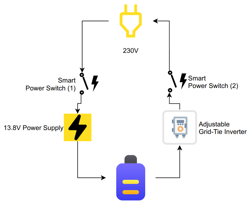
Architecture of the adaptive electricity feed-in system

The following parts are used:

Folgende Komponenten werden verwendet:


  • Aubess - Power Monitor Switch 16A (OpenBK) - approximately 2 Euro
  • Aubess - Power Monitor Switch 16A (OpenBK) - ca. 2 Euro
  • HP HSTNS-PL11 - Power Supply 1200W - approximately 30 Euro
  • HP HSTNS-PL11 - 1200-W-Netzteil - ca. 30 Euro
  • Humsienk 12V 320Ah Battery - approximately 250 Euro
  • Humsienk 12-V-/320-Ah-Batterie - ca. 250 Euro
  • Micro Grid Tie Inverter - 500W DC 16-28V - approximately 80 Euro
  • Micro Grid Tie Inverter - 500 W DC, 16-28 V - ca. 80 Euro

The HP HSTNS-PL11 power supply delivers approximately 12V out of the box, which is insufficient for 12V battery charging (requiring approximately 13.8V). The low-voltage side of the SMPS monitors output using a resistive voltage divider (Vref = Vout * R2/(R1 + R2)) connected to a feedback controller or supervisor IC. The IC regulates the power supply to keep the voltage at this sense pin equal to an internal fixed reference voltage. To increase the output voltage to 13.8V, the voltage divider ratio must be altered (e.g., by placing a resistor in parallel with R1 to decrease its resistance). This lowers the sensed voltage at the pin, causing the controller to increase the output voltage until the sense pin returns to its expected reference level. The relationship is linear; that means increasing the output voltage by 8% directly refers to decreasing the resistance of R2 by the same amount (or increasing R1 by 8%).

Das HP-HSTNS-PL11-Netzteil liefert im Auslieferungszustand etwa 12 V. Das reicht zum Laden einer 12-V-Batterie nicht aus, da dafür ungefähr 13,8 V benötigt werden. Auf der Niederspannungsseite überwacht das Schaltnetzteil die Ausgangsspannung über einen Widerstandsspannungsteiler (Vref = Vout * R2/(R1 + R2)), der mit einem Feedback-Controller beziehungsweise Supervisor-IC verbunden ist. Der IC regelt das Netzteil so, dass die Spannung an diesem Messpin einer internen, festen Referenzspannung entspricht. Um die Ausgangsspannung auf 13,8 V zu erhöhen, muss das Teilungsverhältnis angepasst werden, beispielsweise indem ein Widerstand parallel zu R1 geschaltet und dessen effektiver Widerstand dadurch verringert wird. So sinkt die gemessene Spannung am Pin und der Controller erhöht die Ausgangsspannung, bis am Messpin wieder die erwartete Referenzspannung anliegt. Der Zusammenhang ist linear: Eine Erhöhung der Ausgangsspannung um 8 % entspricht direkt einer Verringerung von R2 um denselben Betrag beziehungsweise einer Erhöhung von R1 um 8 %.


Next part is the control of the Battery-Management-System (BMS) of the Humsienk Battery. The standard way for communication with the BMS is over BLE in combination with the manufacturer's app. In terms of automation this approach is not useful. To be able to control it using a Linux host (e.g., a Raspberry Pi), there is the GitHub project called aiobmsble. It allows connecting via BLE to the BMS and extracting the available data in JSON format. Later it can be used in combination with a REST API to deploy the data over HTTP. For safety reasons the original driver Python script humsienk_bms.py only allows read operations. To be able to control the states of the MOSFETs (CHG and DSG), reverse engineering of the manufacturer's BLE byte protocol is needed.

Als Nächstes folgt die Steuerung des Batteriemanagementsystems (BMS) der Humsienk-Batterie. Standardmäßig erfolgt die Kommunikation mit dem BMS über BLE in Verbindung mit der App des Herstellers. Für eine Automatisierung ist dieser Ansatz ungeeignet. Um das BMS über einen Linux-Host, beispielsweise einen Raspberry Pi, steuern zu können, steht das GitHub-Projekt aiobmsble zur Verfügung. Damit lässt sich über BLE eine Verbindung zum BMS herstellen und die verfügbare Information im JSON-Format auslesen. Später können diese Daten mithilfe einer REST-API über HTTP bereitgestellt werden. Aus Sicherheitsgründen erlaubt das ursprüngliche Python-Treiberskript humsienk_bms.py ausschließlich Lesezugriffe. Um die Zustände der MOSFETs CHG und DSG steuern zu können, muss daher das BLE-Byte-Protokoll des Herstellers mittels Reverse Engineering analysiert werden.
Reverse Engineering and BMS Control

Reverse Engineering und BMS-Steuerung

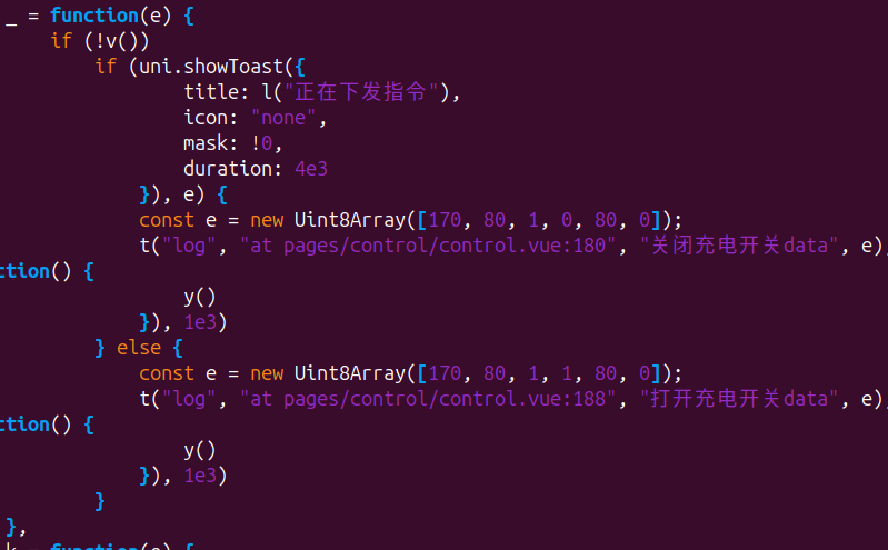
For educational purpose the reverse engineering is done using JADX to decompile the APK. Taking a look at the source code, the app is built using the uni-app framework for cross-platform support. By looking at the files it seems that the logic is stored in the app-service.js file. To get a readable format (for structuring the one-liner), the online tool js-beautify comes in handy. Next step: understanding the code - there is a function named writeData, which is called with 8-bit arrays containing different values. These decimal values represent the commands that are used to control the functions of the BMS. A simple approach to find the values that refer to charge/discharge is to search for the Uint8Array keyword. By translating Chinese to English it becomes clear that the following frame is used to set charging, as shown in the figure below.

Zu Lernzwecken wird das Reverse Engineering mit JADX durchgeführt, um die APK zu dekompilieren. Ein Blick in den Quellcode zeigt, dass die App für plattformübergreifende Unterstützung mit dem uni-app-Framework erstellt wurde. Anhand der Dateien ist davon auszugehen, dass die Logik in app-service.js gespeichert ist. Um den aus einer einzigen Zeile bestehenden Code lesbar zu strukturieren, ist das Onlinewerkzeug js-beautify hilfreich. Im nächsten Schritt muss der Code verstanden werden: Es gibt eine Funktion namens writeData, die mit 8-Bit-Arrays unterschiedlicher Werte aufgerufen wird. Diese Dezimalwerte stellen die Befehle dar, mit denen die Funktionen des BMS gesteuert werden. Ein einfacher Ansatz, die für Laden und Entladen zuständigen Werte zu finden, ist die Suche nach dem Schlüsselwort Uint8Array. Nach der Übersetzung aus dem Chinesischen ins Englische wird deutlich, dass der folgende Frame zum Aktivieren des Ladevorgangs verwendet wird.

Decompiled application code showing the BMS charging command

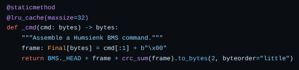
Converting the array [170, 80, 1, 0, 80, 0] to hex results in: AA 50 01 00 50 00. By analyzing it, the structure is: AA (Header), cmd, 0x01 (write flag), value (on/off), checksum_lo, checksum_high. This can be verified by inspecting the code for assembling a read command in humsienk_bms.py, where the CRC calculation is also located.

Die Umwandlung des Arrays [170, 80, 1, 0, 80, 0] in Hexadezimalwerte ergibt: AA 50 01 00 50 00. Die Analyse zeigt folgende Struktur: AA (Header), cmd, 0x01 (Schreib-Flag), value (Ein/Aus), checksum_lo, checksum_high. Dies lässt sich anhand des Codes zum Zusammensetzen eines Lesebefehls in humsienk_bms.py überprüfen, in dem sich auch die CRC-Berechnung befindet.

Read-command implementation in humsienk_bms.py

By taking a closer look, we are missing the value, which makes sense because it's a read command. To implement a write we create a clone of the read function and modify the return part to: return BMS._HEAD + bytes([cmd, 0x01, int(value)]) + crc_sum(crc_basis).to_bytes(2, byteorder="little"). I will call it _write_cmd. With this frame we are now able to perform a write by calling the BMS._await_msg(frame) function using frame: Final[bytes] = BMS._write_cmd(cmd, int(state)). The same function can be used for controlling the discharge MOSFET, which is exactly the same, only using 0x51 instead of 0x50 as the cmd part of the frame. After testing the modified code, the reverse engineering was successful. Info: the information about the commands is also available in the docs of the aiobmsble project.

Bei genauerer Betrachtung fehlt der Wert, was sinnvoll ist, da es sich um einen Lesebefehl handelt. Für die Implementierung eines Schreibvorgangs wird die Lesefunktion kopiert und der Rückgabeteil wie folgt geändert: return BMS._HEAD + bytes([cmd, 0x01, int(value)]) + crc_sum(crc_basis).to_bytes(2, byteorder="little"). Diese Funktion nenne ich _write_cmd. Mit diesem Frame kann nun ein Schreibvorgang durchgeführt werden, indem die Funktion BMS._await_msg(frame) mit frame: Final[bytes] = BMS._write_cmd(cmd, int(state)) aufgerufen wird. Dieselbe Funktion kann den Entlade-MOSFET steuern; der einzige Unterschied besteht darin, im cmd-Teil des Frames 0x51 statt 0x50 zu verwenden. Der Test des geänderten Codes bestätigt, dass das Reverse Engineering erfolgreich war. Hinweis: Informationen zu den Befehlen sind ebenfalls in der Dokumentation des Projekts aiobmsble verfügbar.

To be able to get the information from any device in the network, a REST API is used. FastAPI is a modern web framework for building APIs using Python. The implementation is not difficult, so it will not be explained in detail. In simple words, it only needs to run a modified version of the example script from aiobmsble named "find BLE device and print sensor data", which uses the added write function explained above. After the implementation, the battery can be controlled using the API and calling the implemented POST methods /charge and /discharge, as well as the GET method /status.

Damit die Informationen von jedem Gerät im Netzwerk abgerufen werden können, wird eine REST-API verwendet. FastAPI ist ein modernes Webframework zur Entwicklung von APIs mit Python. Die Implementierung ist nicht schwierig und wird deshalb nicht im Detail erläutert. Vereinfacht gesagt muss lediglich eine angepasste Version des Beispielskripts find BLE device and print sensor data aus aiobmsble ausgeführt werden, welche die zuvor ergänzte Schreibfunktion nutzt. Nach der Implementierung lässt sich die Batterie über die API steuern. Dazu werden die POST-Methoden /charge und /discharge sowie die GET-Methode /status aufgerufen.

Automated System Control

Automatisierte Systemsteuerung

The last part missing is controlling the battery and the relays in combination (e.g. charge, discharge). Since bash is the standard terminal in Linux, a bash script is a reasonable option to use. To achieve an intelligent control system, it has to make decisions based on rules that need to be defined. The following questions have to be answered:

Als letzter Teil fehlt die kombinierte Steuerung der Batterie und der Relais, beispielsweise beim Laden und Entladen. Da Bash das Standardterminal unter Linux ist, bietet sich dafür ein Bash-Skript an. Eine intelligente Steuerung muss Entscheidungen anhand zuvor festgelegter Regeln treffen. Dazu sind die folgenden Fragen zu beantworten:

  1. Which indicator should be used to make decisions and control the system?
    Answer: fixed power thresholds for e.g. start/stop charging/discharging.
  2. Welche Kenngröße soll für Entscheidungen und zur Steuerung des Systems verwendet werden?
    Antwort: feste Leistungsschwellenwerte, beispielsweise zum Starten und Stoppen des Lade- oder Entladevorgangs.
  3. How can constant switching caused by inconsistent solar power be avoided?
    Answer: average the current power with values from the last 15 minutes and combine it with hysteresis, e.g. charging on at 1000W and charging off at 500W.
  4. Wie lässt sich ständiges Schalten aufgrund schwankender Solarleistung vermeiden?
    Antwort: Mittelwertbildung der aktuellen Leistung mit den Werten der letzten 15 Minuten und Kombination mit einer Hysterese, beispielsweise Laden ein bei 1000 W und Laden aus bei 500 W.
  5. Which system states can be defined and what are the relay states for each component?
    Answer: off, power, charging, discharging, undefined (relay states are shown in the code).
  6. Welche Systemzustände können definiert werden und welche Relaiszustände gelten für die einzelnen Komponenten?
    Antwort: aus, Stromversorgung, Laden, Entladen und undefiniert (die Relaiszustände sind im Code dargestellt).

The smart switches have the OpenBK firmware installed. This makes them controllable over a simple GET request. Instead of fixed IP addresses, mDNS is used to address the devices. For safety reasons advanced error handling will also be implemented. The structure of the script will be as follows. A retry function is used to avoid failing if the first attempt to connect to a webserver fails. To request the data from all devices, a get_data function is used, which stores the responses in defined variables for each device. The function get_state uses the data stored in the variables and extracts the current state the devices are in. In this function, these individual states are checked against defined states that represent a system state (e.g. charging, discharging etc.). To set a new system state, the function set_state is used. Finally, the main function holds the control logic, requests the current solar power from a database and decides based on rules whether the system state should change. A Redis database will be used to expose the real-time data for access by different apps. Info: The source code for the bash script is published below.

Auf den Smart Switches ist die OpenBK-Firmware installiert. Dadurch lassen sie sich über eine einfache GET-Anfrage steuern. Statt fester IP-Adressen wird mDNS zur Adressierung der Geräte verwendet. Aus Sicherheitsgründen wird außerdem eine erweiterte Fehlerbehandlung implementiert. Das Skript ist wie folgt aufgebaut: Eine Retry-Funktion verhindert, dass der Ablauf abbricht, wenn der erste Verbindungsversuch zu einem Webserver fehlschlägt. Die Funktion get_data ruft die Daten aller Geräte ab und speichert die Antworten für jedes Gerät in festgelegten Variablen. get_state verwendet diese Daten und ermittelt den aktuellen Zustand der Geräte. Dabei werden die einzelnen Gerätezustände mit definierten Zuständen verglichen, die jeweils einen Systemzustand wie Laden oder Entladen repräsentieren. Mit set_state wird ein neuer Systemzustand gesetzt. Die Hauptfunktion enthält schließlich die Steuerungslogik, ruft die aktuelle Solarleistung aus einer Datenbank ab und entscheidet anhand der Regeln, ob sich der Systemzustand ändern soll. Eine Redis-Datenbank stellt die Echtzeitdaten für den Zugriff durch verschiedene Apps bereit. Hinweis: Der Quellcode des Bash-Skripts ist weiter unten veröffentlicht.

Conclusion

Fazit

The system has been in use for 3 months now (summer to autumn) and it works without issues. With the setup it is possible to cover the base electricity demand overnight. The used grid-tie inverter can be adjusted manually to match the individual power consumption. In my personal setup it is also combined with a heating rod that produces hot water if there is enough power. The savings in electricity costs cannot be calculated yet due to a too short test period. A demonstration of the system is shown in the time-lapse video below.

Das System ist inzwischen seit drei Monaten, vom Sommer bis in den Herbst, ohne Probleme im Einsatz. Mit dem Aufbau lässt sich der nächtliche Grundstrombedarf decken. Der verwendete Netzwechselrichter kann manuell an den individuellen Stromverbrauch angepasst werden. In meinem persönlichen Aufbau ist er außerdem mit einem Heizstab kombiniert, der bei ausreichender Leistung Warmwasser erzeugt. Die Einsparungen bei den Stromkosten lassen sich aufgrund des bisher zu kurzen Testzeitraums noch nicht berechnen.